
The Control Pod is a module within the Realix ERC system, designed for controlling magnetic locks, or other powered devices in an escape room. It provides two outputs, which require an external power source (5V to 24V DC) and are isolated from the internal electronics using optocouplers. The output voltage matches the voltage of the external power source.
Additionally, the Control Pod includes two digital inputs, making it easy to monitor the status of connected devices, such as digital sensors or buttons. The combination of two outputs and two inputs makes the Control Pod ideal for controlling two doors, each equipped with a magnetic lock and a door sensor.
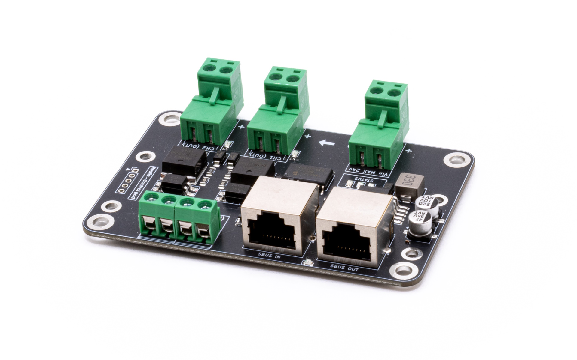
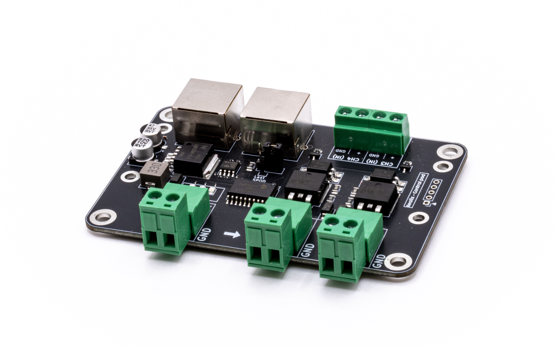
Hardware Configuration
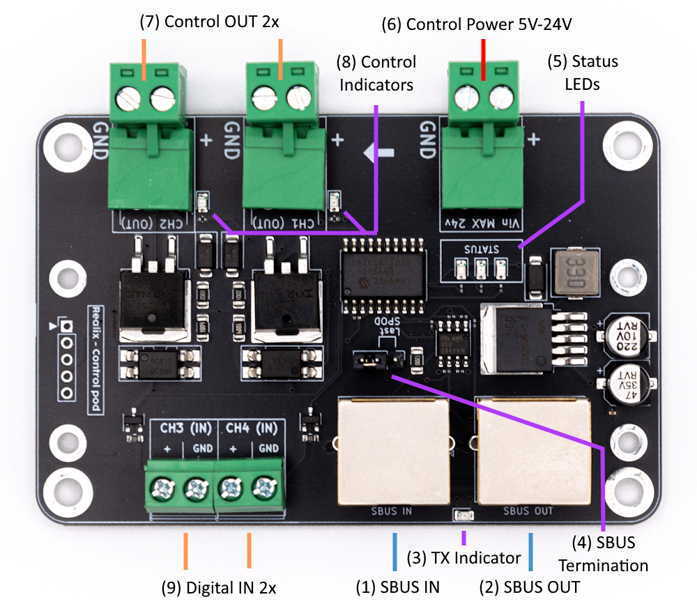
- SBUS IN connector. See SBUS Connector Specification.
- SBUS OUT connector. See SBUS Connector Specification.
- TX Indicator. This LED blinks when data is being transmitted, providing a visual indication that the Pod is actively sending.
- SBUS Termination. The SBUS signal must be terminated on the last SBUS Pod in the chain. All other Pods in the chain should remain unterminated. To enable termination on the last Pod, place the jumper in the “Last SPOD” position.
- Status LED’s.
- Red – The Pod has power but is not receiving any messages.
- Yellow – The Pod is receiving messages from the SBUS Box, but only in discovery mode.
- Green – The Pod is fully operational: ready to receive output commands and send input status.
- Control Power. Connect a dedicated power supply here to drive the two control outputs. The output voltage follows the input voltage. Allowed input range: 5 V to 24 V DC only. Ensure that the external power supply can provide enough current for the connected loads.
- Two Control Outputs. Two isolated solid-state outputs are available on connector (7). They are ideal for driving locks, powering other devices, or switching loads such as LED lights. Each channel supports up to 24 W (equivalent to 2 A at 12 V DC). Ensure that the external power supply can provide sufficient capacity for both outputs.
- Two Indicator LED’s. Each output has a dedicated LED that shows whether the output is active.
- Two digital input channels. Designed for use with a dry contact (e.g., switch, relay, push button) or a logic-level signal (0–5 V). Do not apply higher voltages, mains power, or external supplies to these inputs.
⚠️ Caution: Only voltages between 5 V and 24 V DC are allowed. Using voltages outside this range may damage the device. Ensure the external power supply is rated to provide sufficient power for all connected outputs.
New version’s GND link jumper
The latest version of the Control Pod (not yet in the picture) has a GND link jumper.
The GND Link jumper connects the SBUS ground (0 V) to the ground of the external power supply connected to the Control Pod.
In most installations, the jumper should be installed. This provides a common voltage reference and ensures reliable communication and signal levels.
Remove the jumper only when the external power supply must remain electrically isolated from the SBUS, for example to prevent ground loops or when connecting to an already isolated system.
Recommended: Leave the jumper installed unless you have a specific reason to keep both grounds separated.