
The Multi Pod is a versatile module within the Realix ERC system, designed to support a wide range of interactive escape room components. It provides both digital and analog inputs, while its real strength lies in its expansion capabilities through I²C and serial interfaces.
These interfaces allow the Multi Pod to connect to a large variety of extension modules, including servo drivers, sensors, LCD displays, keypads, and mini mp3 player. Connected to the Realix SBUS, the Multi Pod is fully auto-discoverable, making installation and configuration quick and straightforward.
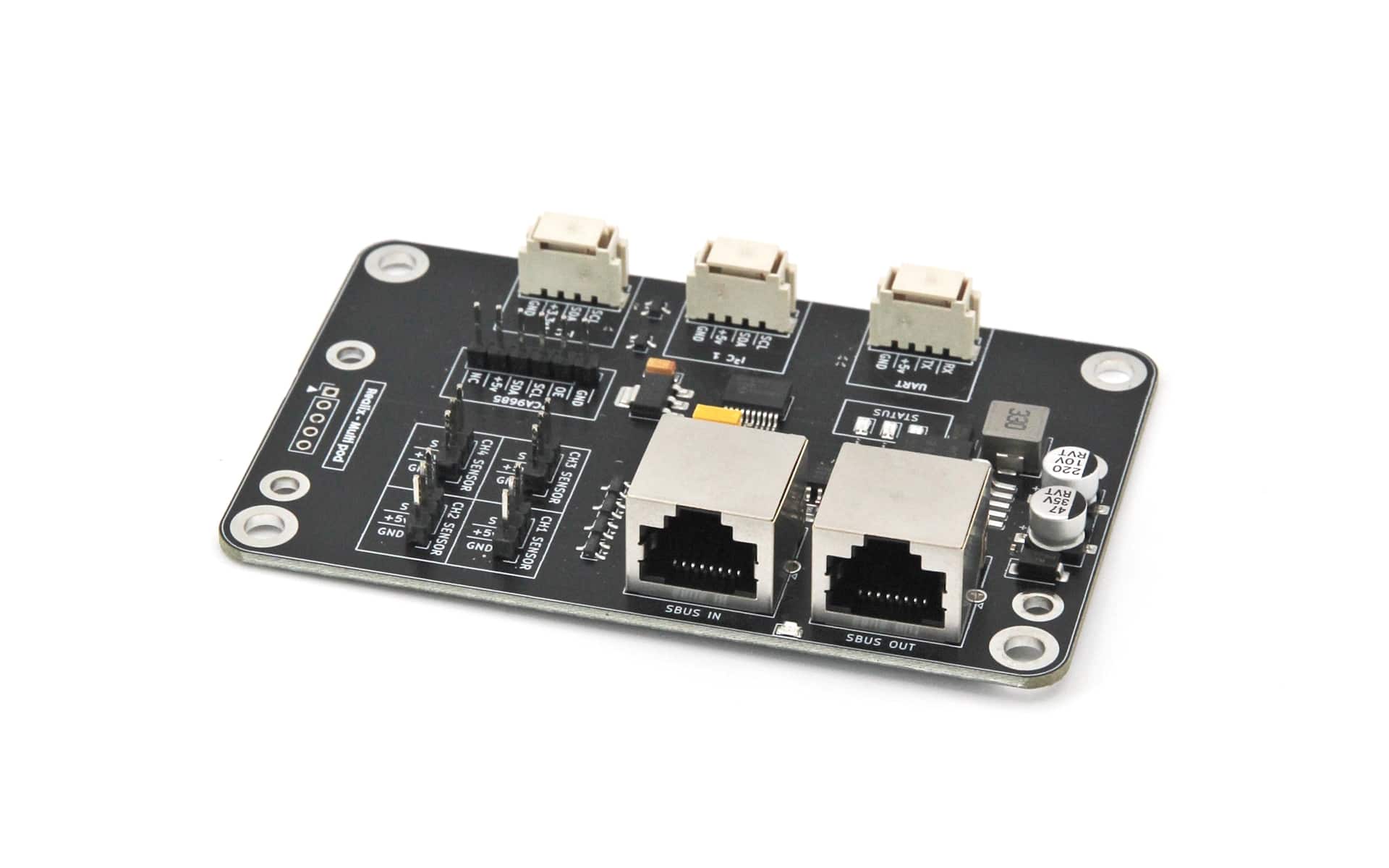
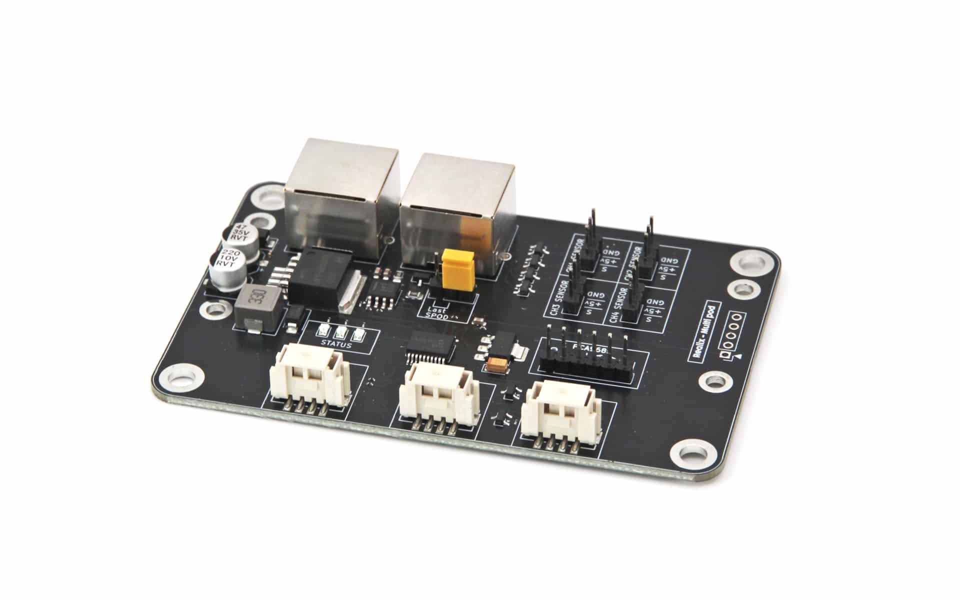
Hardware and Configuration

- SBUS IN connector. See SBUS Connector Specification.
- SBUS OUT connector. See SBUS Connector Specification.
- TX Indicator. This LED blinks when data is being transmitted, providing a visual indication that the Pod is actively sending.
- SBUS Termination. The SBUS signal must be terminated on the last SBUS Pod in the chain. All other Pods in the chain should remain unterminated. To enable termination on the last Pod, place the jumper in the “Last SPOD” position.
- Status LED’s.
- Red – The Pod has power but is not receiving any messages.
- Yellow – The Pod is receiving messages from the SBUS Box, but only in discovery mode.
- Green – The Pod is fully operational: ready to receive output commands and send input status.
- Four analog/digital input channels. Connector uses the Gravity analog sensor layout (GND – VCC – Signal). Do not apply higher voltages, mains power, or external supplies higher then 5V. Each channel can be set as input (digital) or sensor (analog) in the Designer
- Digital: Designed for connection to a dry contact (switch, relay, push button) or a logic-level signal (0–5 V).
- Analog: Provides direct access to the MCU pin for voltage measurement (0–5 V)
- Dedicated connector for connecting a PCA9685 16-channel PWM/Servo controller module. The connector provides an I²C interface along with an additional OE (Output Enable) signal, allowing all connected servos to be enabled or disabled simultaneously using a single control signal.
- I²C Connector 3.3V (Grove Compatible). Provides a 3.3V I²C interface for connecting supported sensors and other expansion modules.
- I²C Connector 5V (Grove Compatible). Provides a 5V I²C interface for connecting supported sensors and other expansion modules.
- Serial Connector 5V (Grove Compatible). Provides a 5V serial interface for connecting supported sensors and other expansion modules
Note: The Grove connector is a simple 4-pin connector system that combines power and I²C communication in a single cable. It is widely used for sensors, displays, and other expansion modules, making connections quick and reliable. For more information, see the Seeed Studio Wiki
The Pod input/output/sensor/controller configuration is done in the device view of the designer. Refer to the box description: Connecting the Box to the ERC.
Multiple firmware versions
To support a wide range of sensors and control modules, the Multi Pod is available with different firmware versions. When ordering, please specify which sensor or control module you intend to use so the appropriate firmware can be installed on your Multi Pod..
- Multi Pod – Sensor
- Multi Pod – Servo
- Multi Pod – Interact
Supported sensors and expansion modules
The Multi Pod supports a growing range of sensors and control modules through its I²C and serial interfaces. We offer firmware support for a selection of commonly used devices, including displays, keypads, servo controllers, audio modules, and various sensors.
However, the Multi Pod is not limited to the devices listed in our documentation. If the sensor or control module you wish to use is not currently supported, we may be able to add support for it through a firmware update.
If you have a specific device in mind, please contact us at [email protected]. We are always interested in expanding the capabilities of the Multi Pod and supporting new hardware for your projects.
PCA9685 PWM module, Servo Driver
The PCA9685 is a 16-channel PWM controller that is used within the Realix ERC system as a servo driver. Connected directly to the Multi Pod, it allows up to 16 servos to be controlled independently. An additional OE (Output Enable) signal is available, allowing all servo control signals to be disabled simultaneously when required.

The PCA9685 board itself is powered by the Multi Pod, but the servos must be powered from an external power supply connected to the board’s screw terminals. Make sure the power supply is sized appropriately for the number and type of servos being used, as multiple servos moving simultaneously can require a substantial amount of current.
The external servo supply must not exceed 6V.
LCD1602, LCD1604 and LCD2004
The Multi Pod supports standard character LCD displays such as the LCD1602, LCD1604, and LCD2004. These displays provide a simple and reliable way to present text, numbers, hints, codes, and game information to players. The display size indicates the number of characters and lines available, for example 16×2, 16×4, or 20×4 characters.
To connect one of these displays to the Multi Pod, it must be equipped with a PCF8574 I²C (IIC) interface module. This small adapter converts the parallel LCD interface into an I²C connection, allowing the display to be connected using only four wires: power, ground, SDA, and SCL. The PCF8574 module must operate at 5V.
More to come
The Multi Pod is based on flexible I²C and serial interfaces, making it possible to support a wide variety of sensors and control modules. At this time, only a limited number of modules are officially supported, but more to come.
If you would like to use a sensor or control module that is not currently supported, please contact us at [email protected]. New modules can often be added through a firmware update.