
Modbus TCP support allows the Realix ERC to control third-party relay modules, PLCs, and other compatible output devices over an Ethernet network. It is intended primarily for driving relays and other devices controlled by ERC outputs where the Control Pod is not sufficient. Examples are switching 230V or motor modules.
⚠️ Modbus is primarily recommended for outputs
Although ERC can read both digital and analogue inputs through Modbus, using Modbus for inputs should generally be avoided. Both Modbus and SBUS inputs are polled, but Modbus polling is considerably slower than the high-speed SBUS polling, which is specifically optimized for this purpose. The additional delay introduced by Modbus can negatively affect buttons, sensors, door contacts, and other player interactions, particularly in puzzles where a fast and immediate response is expected.
How Modbus Works in ERC
ERC uses standard Modbus TCP, normally on TCP port 502.
A Modbus installation is represented by two levels in the Designer:
- Modbus TCP Gateway
The gateway contains the network connection settings, consisting of an IP address and TCP port. A gateway is added to ERC in a similar way to an SBUS Box. However, while SBUS Boxes are discovered automatically, Modbus gateways must be added manually. - Modbus Device
The device represents the actual relay module, PLC, or other Modbus unit. It has a Unit ID and a device profile that defines its available channels and register layout. A Modbus device is added to a Modbus gateway in a similar way to adding an SBUS Pod to an SBUS Box. However, while SBUS Pods are discovered automatically, Modbus devices must be added manually with the correct Unit ID, device profile, and other required settings.
This structure is also used when the Modbus device itself has an Ethernet connection. In that situation, the gateway and the Modbus device refer to the same physical unit:
Modbus TCP Gateway
IP address and TCP port
└── Modbus Device
    Unit ID and device profile
When using an Ethernet-to-RS485 gateway, several Modbus devices can share the same gateway:
Modbus TCP Gateway
└── Modbus Device – Unit ID 1
└── Modbus Device – Unit ID 2
└── Modbus Device – Unit ID 3
The gateway establishes the TCP connection, while each Modbus device is addressed and monitored individually.
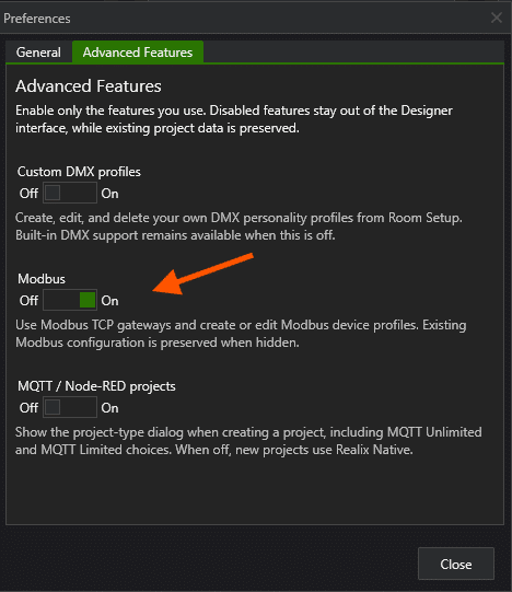
Enabling Modbus Support
Modbus is an advanced feature and must first be enabled in the Designer.
- Open the Realix Designer.
- Select Preferences.
- Open the Advanced Features tab.
- Set Modbus to On.
- Close the Preferences window.
The Modbus TCP Gateway device type and the Modbus Device Profiles panel will now become available.
Preparing the Modbus Hardware
Before adding the device in ERC:
- Give the gateway or Ethernet device a fixed IP address, or create a DHCP reservation.
- Configure it to use standard Modbus TCP.
- The default TCP port is
502. - Determine the Unit ID of each connected Modbus device.
- Make sure every device on the same gateway has a unique Unit ID.
- Ensure that the Realix Server can reach the IP address through the local network.
If a device offers several protocol modes, select Modbus TCP. Do not select transparent TCP, raw serial tunnelling, or RTU-over-TCP.
The Modbus profile in ERC does not configure the physical hardware. Network settings, Unit IDs, and device-specific communication settings must first be configured using the manufacturer’s software or web interface.
Adding a Modbus TCP Gateway
Open your project and navigate to Room Setup → Devices.
- Select New below the device list.
- Select Show all device types.
- Select Modbus TCP Gateway.
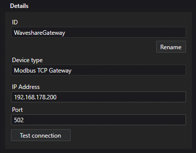
- Enter a unique Device ID.
- Select Create.
The gateway will now appear in the device list.
Enter the following settings:
- IP Address – the address of the gateway or Ethernet Modbus device.
- Port – normally
502.
Select Test connection to check whether the TCP endpoint can be reached.
Note
A successful connection test only confirms that the IP address and TCP port are reachable. It does not verify the Unit ID, device profile, or register configuration.
Adding a Modbus Device
After adding the gateway, the Modbus Devices section appears below its network settings.
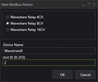
- Select New below the Modbus Devices list.
- Select the required device profile.
- Enter a descriptive Device Name.
- Enter the device’s Unit ID.
- Select OK.
The channels defined by the selected profile are automatically added to the gateway. Repeat these steps when multiple Modbus devices are connected through the same gateway.
A device profile determines:
- The channels offered by the device.
- Whether a channel is an input, output, sensor, or actuator.
- The Modbus data area and register address.
- The original register data format.
- Any required bit index and value conversion.
Built-in Waveshare Relay Profiles
ERC includes standard profiles for the following Waveshare relay modules:
- Waveshare Relay 4CH
- Waveshare Relay 8CH
- Waveshare Relay 16CH
Each profile adds one ERC output channel for every relay on the module.
After adding the module, assign an existing Output object to each channel or create a new Output object directly from the channel list. Device channels and objects can be assigned in the same way as other ERC hardware. See the Realix Designer article for more information about device and object configuration.
Always verify that the exact Waveshare model uses the register layout expected by the selected profile.
Other Modbus Devices
Devices that are not included in the standard library require a custom Modbus device profile.
Custom profiles can be managed on the Designer’s Main page under Modbus Device Profiles. Creating a profile requires the register documentation supplied by the device manufacturer.
Depending on the hardware, a custom profile can contain:
- Digital inputs and outputs.
- Analogue inputs and outputs.
- Individual coils.
- Bits stored inside holding registers.
- 16-bit and 32-bit integer values.
- 32-bit floating-point values.
- Device-specific value ranges and scaling.
Incorrect register addresses, byte order, value formats, or bit indices can result in wrong values or a device showing as disconnected.
Assigning Objects and Testing Outputs
Once the Modbus device has been added, its channels appear in the channel table.
- Select a Modbus device in the Modbus Devices list.
- Optionally enable Show channels for selected Modbus device only.
- Select a channel.
- Assign an existing ERC object or create a new object.
- Select Load Room Setup to start communication.
- Test the assigned outputs from the relevant Objects page.
Outputs can then be used in effect sequences, locks, switches, scripts, and manual Game Host controls just like outputs connected to Realix hardware.
Connection Status
ERC monitors the gateway and every Modbus device separately.
- A green gateway indicator means the TCP connection to the configured IP address and port is active.
- A green Modbus device indicator means that ERC can successfully communicate with that Unit ID and read its configured registers.
- A gateway can therefore be green while one of its Modbus devices is red.
This distinction helps identify the type of problem:
- Gateway red – check the IP address, TCP port, network connection, power, firewall, and Modbus TCP server mode.
- Gateway green, Modbus device red – check the Unit ID, selected profile, register addresses, and device configuration.
- Connection test succeeds, but device remains red – the TCP port is reachable, but the device does not accept the configured Modbus requests.
- Outputs control the wrong channel – check the selected device profile and the manufacturer’s register table.
When a disconnected gateway becomes available again, ERC automatically attempts to reconnect.