
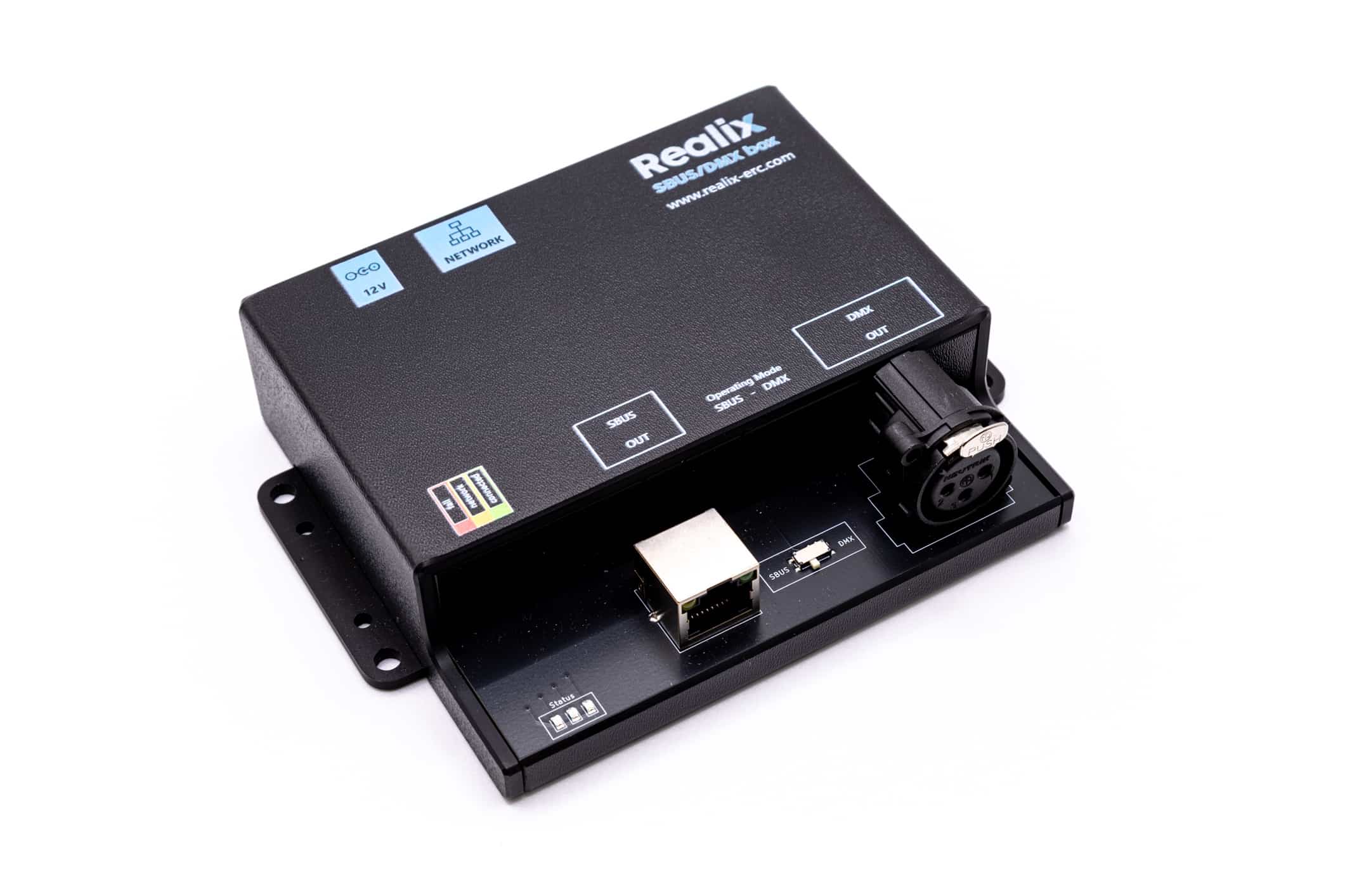
The DMX Box is part of the Realix ERC system, designed to control DMX-compatible lighting and effects within an escape room. It allows integration of dynamic lighting, strobes, and other DMX-controlled devices.
How the DMX Box Works
- Provides one DMX universe, supporting up to 512 DMX channels.
- Communicates with DMX lighting and effects equipment, allowing control over brightness, color, and effects.
- Auto-discoverable, meaning it is automatically detected and configured in the Designer when connected.
Each DMX Box controls one DMX universe. If more channels are required, additional DMX Boxes can be added to the system, each managing a separate universe.
Hardware and Configuration
While the DMX Box is logically a standalone device, it shares its hardware with the SBUS Box. Both are housed in a single SBUS/DMX unit, with a switch that allows selection between SBUS and DMX functionality. In the Designer, this device will appear either as an SBUS Box or a DMX Box, depending on the selected mode.
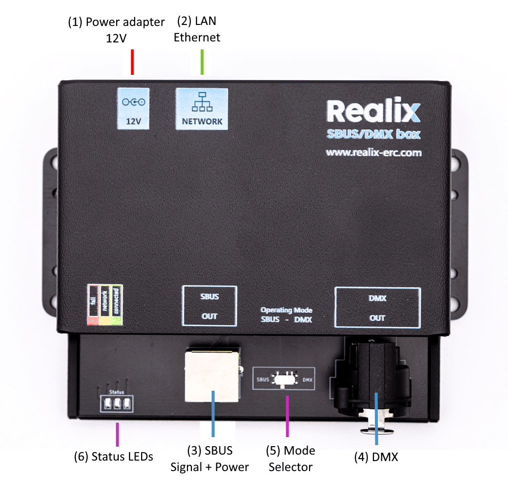
Box description
- Power adapter. See Power Adapter Specification below.
- Ethernet connector to connect it to the LAN. See Connecting the Box to the ERC.
- SBUS connector. See the article describing the Realix SBUS Box
- DMX Connector. See DMX Box connector specification.
- Operating Mode selector that allows it to function either as an SBUS Box or as a DMX Box. The selected mode is only applied during power-up.
- Indicator LEDs: Red – fail, Yellow – network detected, Green – connected and operational; See Connecting the Box to the ERC.
Connecting the Box to the ERC
Setup Instructions
Put the selector for the Operational Mode in the position DMX
Plug in the power supply. Make sure to check the Power Adapter Specification to ensure you’re using the correct adapter. Once connected, the red indicator light will turn on.
Connect the device to your network using the Ethernet port labeled NETWORK; it requires a DHCP-enabled LAN, as static IP configuration is not supported. The box is automatically discoverable regardless of its IP address.
When the device successfully receives an IP address from the DHCP server, the yellow LED will light up. At this point, the device is fully operational and automatically discoverable by the Realix ERC system.
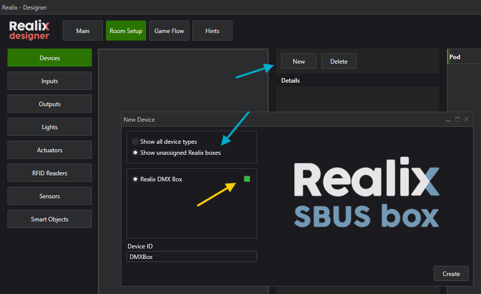
Open the Designer and load your project if it isn’t already open. Navigate to the Room Setup and Devices page, as shown in the image below. Click New to open the New Device dialog, then select “Show unassigned Realix boxes”, as indicated by the blue arrows. The dialog should now display your newly connected DMX Box.
To identify the correct device when multiple boxes of the same type appear in the list, click the green indicator icon (highlighted by the yellow arrow) to make the corresponding yellow LED on the physical box blink.
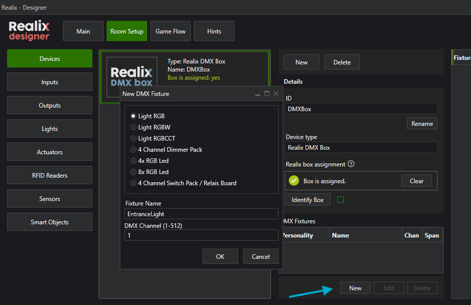
Once the DMX Box has been added, you can begin adding your fixtures. A fixture refers to any DMX-controlled device or object. The configuration that defines the fixture’s DMX channels is called its personality. To learn more about DMX and fixture personalities, see the article on the DMX Personality Library
The image below shows how to add a fixture. When adding a new DMX fixture, you must select a starting DMX channel, which defines where the fixture begins within the 512-byte DMX address space. When the New DMX Fixture dialog opens, the next available DMX address is automatically suggested.
It’s important to note that a DMX channel is not the same as an ERC device channel, the DMX channel simply represents a specific address within the DMX block, while ERC channels are created based on the parts defined in a fixture.
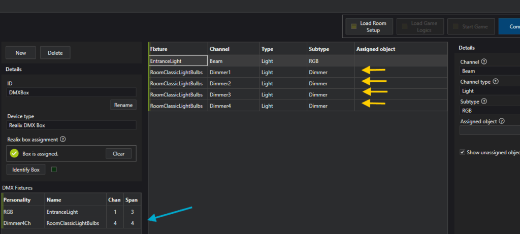
In the next screenshot, you can see how ERC channels are generated from the fixtures. A good example is the added dimmer pack, which can control up to four connected light bulbs. The DMX start channel and channel span are displayed in the fixture definition (indicated by the blue arrow). The corresponding ERC channels created are listed in the device’s channel list (shown by the yellow arrows). Each dimmer can now easily have an object assigned to it.
DMX Connector Specification
We use a 3-pin DMX connector to link lighting fixtures and the DMX controller. It looks like a regular microphone (XLR) plug, but it’s used to send lighting control signals—not sound.
- Pin 1: Ground
- Pin 2: Data (–)
- Pin 3: Data (+)
⚠️ Note: Although it looks similar to audio cables, you should use proper DMX cables to ensure stable communication between devices. Also, remember to place a terminator at the last fixture in the chain to avoid signal issues.
Power Adapter Specification
This specification covers both SBUS and DMX requirements, as they share the same hardware platform.
| Parameter | Specification |
|---|---|
| Type | Stabilized (regulated) DC power supply |
| Input Voltage Range | 100–240 V AC, 50/60 Hz (typical wall adapter input) |
| Output Voltage | 12V DC |
| Output Current | SBUS usage: Minimum 1.5 A DMX usage: Minimum 0.5A |
| Polarity | Center positive |
| Connector Type | DC barrel plug, 5.5 mm outer / 2.1 mm inner diameter |
⚠️ Important:
The power adapter must be used exclusively to power the SBUS/DMX Box.
Do not use this adapter to power any other devices (e.g. electromagnetic locks, relays, or lighting), as doing so may overload the power supply and cause unpredictable system behavior or permanent damage.
Warning
Using a non-stabilized (unregulated) power supply, insufficient current rating, or incorrect voltage may result in:
- Unstable or failed communication between SBUS Box and Pods
- Unstable or failed DMX communication
- Undervoltage at pods, especially at longer cable lengths
- Malfunction or permanent damage to connected electronics
- Excessive heat or electrical noise affecting system reliability
Always verify that the adapter:
- Is regulated/stabilized
- Matches the required voltage and current
- Has a 5.5/2.1 mm center-positive plug
The SBUS cable carries both data and power.
Connecting SBUS cables to standard Ethernet devices can damage or destroy those devices due to the presence of voltage on the cable.
🛑 Only connect Realix SBUS Pods to the SBUS port.
Never connect any non-SBUS or Ethernet-based hardware to these ports.