
The IO Pod is a versatile module within the Realix ERC system, designed to handle input and output (I/O) functions in an escape room. It allows to integrate buttons, switches, sensors, and indicator lights. It is connected to the Realix SBUS and is auto-discoverable.
Hardware and Configuration
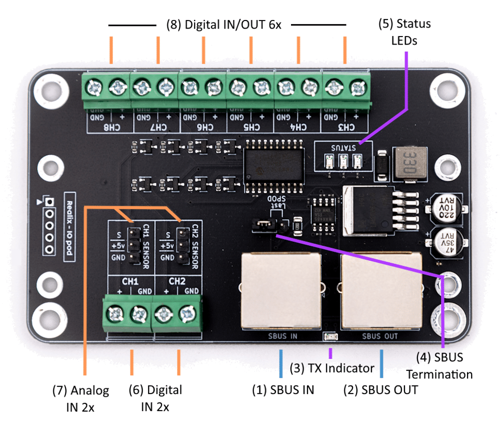
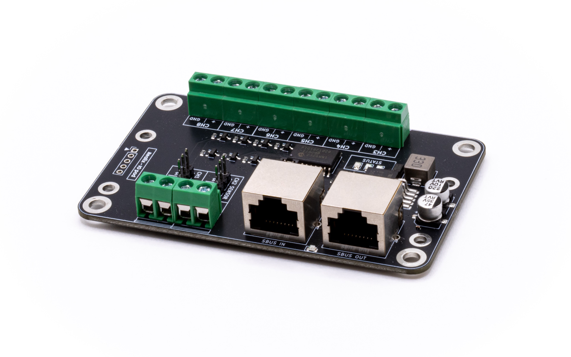
- SBUS IN connector. See SBUS Connector Specification.
- SBUS OUT connector. See SBUS Connector Specification.
- TX Indicator. This LED blinks when data is being transmitted, providing a visual indication that the Pod is actively sending.
- SBUS Termination. The SBUS signal must be terminated on the last SBUS Pod in the chain. All other Pods in the chain should remain unterminated. To enable termination on the last Pod, place the jumper in the “Last SPOD” position.
- Status LED’s.
- Red – The Pod has power but is not receiving any messages.
- Yellow – The Pod is receiving messages from the SBUS Box, but only in discovery mode.
- Green – The Pod is fully operational: ready to receive output commands and send input status.
- Two digital input channels. Designed for connection to a dry contact (switch, relay, push button) or a logic-level signal (0–5 V). Do not apply higher voltages, mains power, or external supplies.
Note: The screw terminal shares its pin with the analog connector, but due to a series resistor it cannot be used for analog measurement. - Two analog input channels (3-pin). Connector uses the Gravity analog sensor layout (GND – VCC – Signal). Provides direct access to the MCU pin for voltage measurement (0–5 V).
Note: This input has less protection than the digital input, use only safe low-voltage signals. - Six configurable input/output channels. Each channel can be set as input or output in the Designer.
- As input: For dry contacts (e.g. switch, relay) or logic-level signals (0–5 V). Do not apply higher voltages, mains power, or external supplies.
- As output: Limited to approx. 15 mA, suitable for driving small LEDs or relays. Not for powering external devices.
The Pod input/output/sensor configuration is done in the device view of the designer. Refer to the box description: Connecting the Box to the ERC.